


Why does voltage imbalance show up quickly when assembling a batch of 3.2V 100Ah LiFePO4 cells in series?

Many customers receive 3.2V 100Ah cells with qualified open-circuit voltage and capacity on individual tests. After two to three months of series-parallel operation, the voltage gap within the string gradually exceeds 80mV. The BMS stays in balancing mode continuously, and balancing loss consumes part of usable capacity. The weak cell hits the protection voltage in advance and forces the whole energy storage system to derate. When testing 3.2V 100Ah LiFePO4 cells before packing, always check both voltage and internal resistance.
This cell has a large single-cell capacity, so inconsistency creates more severe impacts compared with smaller cells. Relying only on factory static capacity and internal resistance sorting is insufficient. Some cells differ in self-discharge rate and hidden polarization resistance, which cannot be identified by static testing. These differences keep expanding as cycles accumulate.
In practical operation for 3.2V 100Ah LiFePO4 cells, do not assemble cells immediately after delivery. Add a recheck after storage plus low-rate charge-discharge matching. Prioritize cells with open-circuit voltage difference within 20mV after seven days of rest and similar internal resistance under 0.2C charge-discharge into the same string. Use cells from the same batch and formation process within one module. Avoid long-term full-charge floating storage after assembly; high SOC accelerates self-discharge divergence and worsens imbalance. Record open-circuit voltage of each string regularly during maintenance. Trigger active balancing once the voltage gap exceeds 50mV, instead of waiting until the deviation becomes severe.
Can you charge 3.2V 100Ah LiFePO4 cells at full power directly in low-temperature environments?
The 3.2V 100Ah is a large-format cell with large electrode area. Lithium ion migration resistance rises at low temperatures, and lithium plating easily occurs on the negative electrode. Many off-grid solar and pastoral energy storage projects apply high-current charging directly when photovoltaic power is available in winter. After several months of operation, capacity drops obviously and internal resistance keeps rising.
The standard recommended charging temperature for this type of cell is above 0°C. Charging current above 0.5C is not recommended below 0°C. Many users confuse the temperature limits for charging and discharging. Discharge can be allowed at low temperatures, while charging has stricter restrictions.
For system matching, set segmented temperature-based charging logic in the BMS. Reduce charging current below 5°C. Activate preheating first when the temperature is below 0°C, and start charging only after cell temperature rises above 5°C. Do not rely on high current through the cell itself for heating. Use external heating films and temperature controllers for uniform warming to avoid excessive internal temperature gradient. If the project operates continuously below zero, confirm whether the cell uses low-temperature electrolyte before purchase. Standard 3.2V 100Ah LiFePO4 cells are not suitable for long-term high-current charging in cold conditions.
What continuous discharge current can 3.2V 100Ah LiFePO4 cells safely handle, and what risks will overload bring?
Many customers pull current directly according to load demand and run cells continuously at 0.8C, 1C or higher, judging safety only by case temperature. Voltage remains stable during short high-current discharge, but the tabs and current collectors of large-format cells bear heavy load. Sustained over-spec discharge causes concentrated heat at tabs, accelerates electrolyte aging, gradually raises internal resistance and speeds up capacity fade.
For conventional commercial 3.2V 100Ah LiFePO4 large cells, the safe continuous discharge rate is mostly 0.5C (50A). Short pulse discharge can reach 1C (100A), but pulse mode cannot run continuously. Current carrying capacity varies greatly between single-tab and dual-tab versions. Check the continuous discharge rating on the datasheet before purchase instead of estimating the current limit simply based on the 100Ah capacity.
Reserve current margin in system design and keep continuous load current within the rated continuous value. Add capacitor buffers for impulse high-power loads to reduce repeated large current shocks on cells. Design cooling air channels inside the module and focus on tab temperature monitoring. Case temperature has obvious lag, so overheating at tabs cannot be detected early by measuring only shell surface temperature.
What voltage level works best for long-term storage of new 3.2V 100Ah LiFePO4 cells, and can deeply depleted units be recovered?
Many customers purchase 3.2V 100Ah cells in bulk and do not assemble them right away. Storing them fully charged for months leads to widespread voltage imbalance and abnormal self-discharge. Some cells keep dropping during storage below 2.5V, and users are unsure whether they should be scrapped directly.
The proper storage voltage for large LiFePO4 cells is 3.20V to 3.25V. Do not store them at 3.65V full SOC for a long time. High voltage accelerates self-discharge and aging. Keep the storage area away from light with stable temperature between 10–25°C. Humid surroundings speed up terminal corrosion and introduce extra leakage current.
Cells staying above 2.8V can generally be activated through low-current charge and discharge. Once voltage falls below 2.5V, irreversible side reactions have started inside. Do not integrate them into energy storage systems. Even if the voltage is restored, these cells suffer unstable internal resistance and shortened cycle life. They will become persistent weak points and trigger frequent faults after grouping. Sample and check open-circuit voltage regularly during stock storage to avoid large batches of cells sitting under deep depletion.
Is independent temperature sensing required for every 3.2V 100Ah LiFePO4 cell during series assembly?
Some projects cut costs by placing only one or two temperature probes per module, assuming LiFePO4 is safe enough without multi-point temperature monitoring. However, a single 3.2V 100Ah cell has large volume and capacity with uneven internal temperature distribution. If one cell has abnormal internal resistance and generates more heat, single-point sensing cannot capture this deviation.
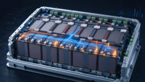
By the time the probe detects obvious temperature rise, the cell abnormality has already developed to an advanced stage. BMS thermal protection will be delayed and risks increase.
The practical approach is to attach temperature sensors on every 3.2V 100Ah cell surface, preferably near the heat-generating tab area. The BMS collects both voltage and temperature signals. Trigger current limiting or shutdown immediately once any cell exceeds temperature or voltage thresholds. Independent monitoring is also required for parallel branches; do not combine multiple parallel cells under one signal channel. This practice is especially important for off-grid solar storage and residential energy storage systems.
How to tell whether a faded 3.2V 100Ah LiFePO4 cell can remain in its original module?
After around one year of operation, many users only check open-circuit voltage and keep cells in service as long as readings look similar, ignoring the gap in actual usable capacity. Inside one string, one cell may only deliver 85Ah while others remain around 95Ah. The weak cell hits the cut-off voltage first during charge and discharge and caps the overall usable capacity of the battery pack.
Open-circuit voltage alone cannot evaluate cell health. A simple field test method is to run a full 0.2C charge-discharge cycle on the suspicious cell and record actual capacity, charge plateau and temperature rise. Remove it directly if measured capacity drops below 80% of nominal value, the charge plateau shifts downward obviously, or its temperature rise is much higher than other cells under the same current.
This rule also applies to second-life regrouping. Forcing cells with inconsistent attenuation characteristics into one group raises maintenance frequency, constant alarms and frequent balancing, which increases labor and service costs over time.
What cascading failures will rusted terminals and loose bolts trigger on 3.2V 100Ah LiFePO4 cells?
3.2V 100Ah cells carry relatively high operating current, so connection points are high-failure spots on site. Insufficient bolt torque and unprotected copper-aluminum terminals lead to oxidation and rust in humid outdoor environments, which gradually increases contact resistance.
Higher contact resistance creates concentrated heat at connections under large current. The local high temperature transfers to cell tabs, accelerates aging and may even burn terminals or cause sparks. A large number of field failures originate from poor assembly instead of inherent cell defects.
Tighten bolts following the torque recommendation from the manufacturer. Clean contact surfaces, apply conductive grease and wrap with waterproof insulation. Check terminal temperature difference during routine inspection. Retighten and remove oxidation once heating is found. Do not directly connect dissimilar conductors to prevent continuous galvanic corrosion.